What you'll be able to do本章學習成果
- Conduct air-standard analyses of the Otto, Diesel, and Dual cycles, sketching p–v and T–s diagrams and evaluating each state.對奧圖、柴油與複合循環進行空氣標準分析,繪製 p–v 與 T–s 圖,並評估各狀態。
- Determine net work, thermal efficiency, and mean effective pressure for reciprocating engines.求出往復式引擎的淨功、熱效率與平均有效壓力。
- Analyze gas-turbine plants on the Brayton cycle and its modifications — regeneration, reheat, and intercooling.以布雷頓循環及其改良(回熱、再熱與中間冷卻)分析燃氣渦輪機電廠。
Key equations重要公式
Engine terminology引擎術語
In a piston engine the piston sweeps between top dead center (TDC, minimum cylinder volume) and bottom dead center (BDC, maximum volume). Two quantities frame everything that follows:在活塞引擎中,活塞往返於上止點(TDC,最小缸內容積)與下止點(BDC,最大容積)之間。下文皆建立於兩個量之上:
- Compression ratio $r = V_{BDC}/V_{TDC}$ — the volume at bottom dead center divided by that at top dead center.壓縮比 $r = V_{BDC}/V_{TDC}$—下止點容積除以上止點容積。
- Displacement volume — the volume swept by the piston moving from TDC to BDC.排氣量(行程容積)—活塞由上止點移至下止點所掃過的容積。
The mean effective pressure (MEP) is a theoretical constant pressure that, acting on the piston through the power stroke, would produce the same net work as the actual cycle:平均有效壓力(MEP)是一理論上的定壓力,若在做功行程中作用於活塞,將產生與實際循環相同的淨功:
For two engines of equal displacement, the one with the higher MEP produces the greater net work — and, at equal speed, the greater power.對於排氣量相同的兩台引擎,MEP 較高者產生較大的淨功—且在轉速相同時輸出較大的功率。
Air-standard analysis空氣標準分析
Real combustion engines are complex. An air-standard analysis trades exactness for insight with a set of idealizations:真實的燃燒引擎相當複雜。空氣標準分析以一組理想化假設牺牲精確性以換取洞見:
- A fixed amount of air as an ideal gas is the working fluid throughout.全程以定量的理想氣體空氣作為工作流體。
- Combustion is replaced by heat transfer from an external source.以來自外部熱源的熱傳遞取代燃燒。
- There are no intake/exhaust strokes; a constant-volume heat-rejection process completes the cycle.不考慮進氣與排氣行程;以一個定容排熱過程完成循環。
- All processes are internally reversible.所有過程皆為內部可逆。
In the cold air-standard analysis used by the simulator below, specific heats are held constant at room-temperature values: $k=1.4$, $c_v=0.718$, $c_p=1.005$ kJ/kg·K. The Otto, Diesel, and Dual cycles differ only in how heat addition is modeled — constant volume, constant pressure, or both.在下方模擬器所用的冷空氣標準分析中,比熱保持在室溫定值:$k=1.4$、$c_v=0.718$、$c_p=1.005$ kJ/kg·K。奧圖、柴油與複合循環僅在加熱方式的建模上有別—定容、定壓或兩者兼具。
The Otto cycle奧圖循環
The Otto cycle — the air-standard model of the spark-ignition engine — consists of four internally reversible processes:奧圖循環—火花點火引擎的空氣標準模型—由四個內部可逆過程組成:
- 1–2 Isentropic compression.1–2 等熵壓縮。
- 2–3 Constant-volume heat addition (models combustion).2–3 定容加熱(模擬燃燒)。
- 3–4 Isentropic expansion (the power stroke).3–4 等熵膨脹(做功行程)。
- 4–1 Constant-volume heat rejection.4–1 定容排熱。
Because both heat-transfer processes are at constant volume, the thermal efficiency reduces to a remarkably clean result that depends only on compression ratio:因兩個熱傳遞過程皆為定容,熱效率簡化為一個非常簡潔、僅取決於壓縮比的結果:
Derivation推導 Where Eq. 9.8 comes from第 9.8 式的由來 ›
1. Start from the efficiency definition.1. 從效率定義出發。 For any cycle the thermal efficiency is the net work over the heat supplied, which the first law lets us write in terms of heat alone:任何循環的熱效率為淨功除以供給的熱量,由第一定律可僅以熱量表示: $$\eta = \frac{w_{net}}{q_{in}} = 1 - \frac{q_{out}}{q_{in}}.$$
2. Both heat transfers are at constant volume.2. 兩次熱傳遞皆為定容。 With constant specific heats (cold air-standard), the constant-volume heat addition 2→3 and rejection 4→1 give:在比熱為常數的冷空氣標準下,定容加熱 2→3 與排熱 4→1 為: $$q_{in}=c_v(T_3-T_2),\qquad q_{out}=c_v(T_4-T_1).$$ $$\eta = 1 - \frac{T_4-T_1}{T_3-T_2}.$$
3. Apply the isentropic relations.3. 套用等熵關係。 Compression 1→2 and expansion 3→4 are isentropic, and the constant-volume steps fix $V_1=V_4$ and $V_2=V_3$ — so both share the same volume ratio $r=V_1/V_2$:壓縮 1→2 與膨脹 3→4 為等熵,定容步驟使 $V_1=V_4$、$V_2=V_3$,故兩者具相同體積比 $r=V_1/V_2$: $$\frac{T_2}{T_1}=r^{\,k-1},\qquad \frac{T_3}{T_4}=r^{\,k-1}.$$
4. The temperature differences cancel.4. 溫差相消。 Since $T_2/T_1 = T_3/T_4$, it follows that $T_3/T_2 = T_4/T_1$. Factor $T_1$ and $T_2$ out of the ratio and the bracketed terms are identical:因 $T_2/T_1 = T_3/T_4$,可得 $T_3/T_2 = T_4/T_1$。將 $T_1$、$T_2$ 提出後,括號內的項完全相同: $$\eta = 1 - \frac{T_1\!\left(\tfrac{T_4}{T_1}-1\right)}{T_2\!\left(\tfrac{T_3}{T_2}-1\right)} = 1 - \frac{T_1}{T_2}=1-\frac{1}{r^{\,k-1}}.$$
Efficiency climbs with compression ratio — which is why engineers push r as high as they can. In spark-ignition engines the limit is autoignition ("knock"), which caps practical compression ratios around 9.5–11.5 on unleaded gasoline.效率隨壓縮比上升—這正是工程師盡可能提高 r 的原因。在火花點火引擎中,極限在於自燃(「爆震」),它將無鈙汽油的實用壓縮比限在約 9.5–11.5。
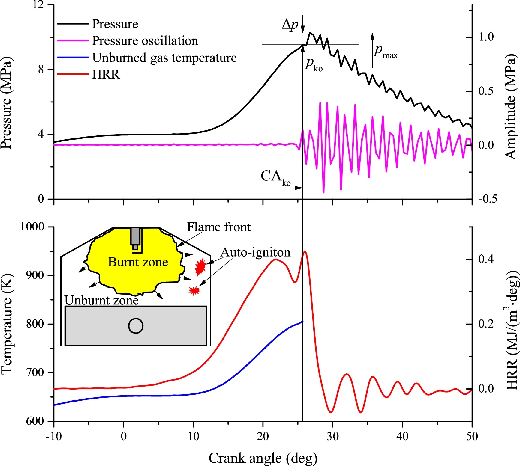
In normal spark-ignition operation the spark plug fires and a flame front travels smoothly across the chamber, burning the mixture progressively. Knock is when the unburned end-gas ahead of that flame — already hot and highly compressed — autoignites on its own before the flame reaches it.在正常的火花點火運轉中,火星塞點火後火焰前緣平順地掃過燃燒室,逐步燃燒混合氣。爆震是指火焰尚未到達前,前方未燃的端氣——已處於高溫高壓——自行提前自燃。
The two flame fronts collide and the sudden local pressure spike sets up a sharp pressure wave that rings the cylinder walls — the metallic "knocking" sound. Sustained knock erodes pistons and bearings, so the compression ratio must stay below the threshold where the end-gas would autoignite.兩道火焰相遇,瞬間的局部壓力尖峰激起陡峭壓力波並衝擊缸壁,發出金屬「敲擊」聲。持續爆震會侵蝕活塞與軸承,故壓縮比必須維持在端氣自燃門檻之下。
A fuel's resistance to this is its octane rating: higher-octane fuel tolerates a higher compression ratio before knocking, which is precisely why it unlocks more of the efficiency gain Eq. 9.8 promises.燃料抵抗爆震的能力即其辛烷值:高辛烷值燃料可在更高壓縮比下才發生爆震,這正是它能釋放第 9.8 式所允諾效率增益的原因。
The Diesel cycle柴油循環
The Diesel cycle models the compression-ignition engine. It differs from Otto in one process: heat is added at constant pressure rather than constant volume, giving a two-step power stroke.柴油循環模擬壓縮點火引擎。它與奧圖僅在一個過程上不同:加熱是在定壓而非定容下進行,形成兩階段的做功行程。
- 1–2 Isentropic compression.1–2 等熵壓縮。
- 2–3 Constant-pressure heat addition.2–3 定壓加熱。
- 3–4 Isentropic expansion.3–4 等熵膨脹。
- 4–1 Constant-volume heat rejection.4–1 定容排熱。
A new parameter appears — the cutoff ratio, the volume expansion during constant-pressure heat addition:出現一個新參數—限斷比(截止比),即定壓加熱期間的容積膨脹:
With it, the efficiency is:以其表示,效率為:
Derivation推導 Where Eq. 9.13 comes from第 9.13 式的由來 ›
1. Efficiency from the two heat transfers.1. 由兩次熱傳遞表示效率。 Heat is now added at constant pressure (2→3) and rejected at constant volume (4→1), so the two use different specific heats:熱量於定壓下加入(2→3)、於定容下排出(4→1),故兩者使用不同比熱: $$\eta = 1 - \frac{q_{out}}{q_{in}} = 1 - \frac{c_v(T_4-T_1)}{c_p(T_3-T_2)} = 1 - \frac{1}{k}\,\frac{T_4-T_1}{T_3-T_2}.$$
2. Express every temperature via state 1.2. 以狀態 1 表示各溫度。 Using $r=V_1/V_2$ and $r_c=V_3/V_2$, and noting $V_4=V_1$ so $V_3/V_4 = r_c/r$:利用 $r=V_1/V_2$ 與 $r_c=V_3/V_2$,並注意 $V_4=V_1$,故 $V_3/V_4 = r_c/r$: $$T_2 = T_1\,r^{\,k-1},\quad T_3 = T_2\,r_c = T_1\,r^{\,k-1}r_c,\quad T_4 = T_3\!\left(\tfrac{r_c}{r}\right)^{k-1}=T_1\,r_c^{\,k}.$$
3. Substitute and simplify.3. 代入並化簡。 The differences become $T_4-T_1=T_1(r_c^{\,k}-1)$ and $T_3-T_2=T_1\,r^{\,k-1}(r_c-1)$. Dividing, $T_1$ cancels and $r^{\,k-1}$ factors out:兩差為 $T_4-T_1=T_1(r_c^{\,k}-1)$ 與 $T_3-T_2=T_1\,r^{\,k-1}(r_c-1)$。相除後 $T_1$ 相消、$r^{\,k-1}$ 提出: $$\eta_{Diesel} = 1 - \frac{1}{r^{\,k-1}}\left[\frac{r_c^{\,k}-1}{k\,(r_c-1)}\right].$$
The bracketed term is always greater than one, so for the same compression ratio a Diesel cycle is slightly less efficient than Otto. But because compression-ignition engines aren't knock-limited, they run at much higher $r$ — and win overall.括號內的項恒大於一,所以在相同壓縮比下,柴油循環略逆於奧圖。但因壓縮點火引擎不受爆震限制,得以在高得多的 $r$ 下運轉—整體而言反而勝出。
The Dual cycle複合循環
Real engine indicator diagrams look like neither pure Otto nor pure Diesel. The Dual cycle splits heat addition into two steps — constant volume then constant pressure — to mimic the actual pressure–volume trace more closely. It reduces to Otto (no constant-pressure part) or Diesel (no constant-volume part) as limiting cases. Like both, its efficiency rises with compression ratio.真實引擎的示功圖既不像純奧圖、也不像純柴油。複合循環將加熱分為兩個步驟—先定容再定壓—以更貼近實際的壓力–容積軌跡。在極限情況下它會退化為奧圖(無定壓部分)或柴油(無定容部分)。與兩者一樣,其效率隨壓縮比上升。
Cycle simulator循環模擬器
Switch between Otto, Diesel, and Brayton, then drag the sliders. Watch the cycle redraw on both the p–v and T–s diagrams while efficiency, net work, and MEP update live. Try pushing the Otto compression ratio up, or widening the Diesel cutoff ratio.在奧圖、柴油與布雷頓之間切換,再拖動滑桿。觀察循環在 p–v 與 T–s 兩張圖上重繪,同時效率、淨功與平均有效壓力即時更新。試著提高奧圖的壓縮比,或加大柴油的限斷比。
Cold air-standard model, $k=1.4$. Reference state $p_1=100$ kPa.冷空氣標準模型,$k=1.4$。參考狀態 $p_1=100$ kPa。
Otto cycle efficiency奧圖循環效率
Example範例 Effect of compression ratio壓縮比的影響 ›
Given: an air-standard Otto cycle with compression ratio $r=8$, $k=1.4$.已知:一空氣標準奧圖循環,壓縮比 $r=8$、$k=1.4$。
Find: the thermal efficiency.求:熱效率。
Solution.解: $$\eta=1-\frac{1}{r^{\,k-1}}=1-\frac{1}{8^{0.4}}=1-0.435=0.565\ (56.5\%).$$ Raising $r$ raises efficiency — which is why engineers push it until knock intervenes.提高 $r$ 可提升效率——這正是工程師不斷提高壓縮比、直到爆震介入為止的原因。
The Brayton cycle布雷頓循環
Gas-turbine power plants run on the Brayton cycle. In the open arrangement, air is drawn in, compressed, heated by combustion, expanded through a turbine, and exhausted. The air-standard idealization closes the loop with constant-pressure heat rejection:燃氣渦輪機電廠運行於布雷頓循環。在開放式配置中,空氣被吸入、壓縮、經燃燒加熱、通過渦輪機膨脹後排出。空氣標準理想化以定壓排熱封閉此迴路:
- 1–2 Isentropic compression (compressor).1–2 等熵壓縮(壓縮機)。
- 2–3 Constant-pressure heat addition (combustor).2–3 定壓加熱(燃燒室)。
- 3–4 Isentropic expansion (turbine).3–4 等熵膨脹(渦輪機)。
- 4–1 Constant-pressure heat rejection.4–1 定壓排熱。
With both heat transfers at constant pressure, efficiency depends only on the compressor pressure ratio:由於兩次熱傳遞皆為定壓,效率僅取決於壓縮機壓比:
Derivation推導 Where Eq. 9.19 comes from第 9.19 式的由來 ›
1. Efficiency from the two constant-pressure heat transfers.1. 由兩次定壓熱傳遞表示效率。 Heat is added 2→3 and rejected 4→1, both at constant pressure, so each uses $c_p$:熱量於 2→3 加入、4→1 排出,兩者皆為定壓,故各使用 $c_p$: $$\eta = 1 - \frac{q_{out}}{q_{in}} = 1 - \frac{c_p(T_4-T_1)}{c_p(T_3-T_2)} = 1 - \frac{T_4-T_1}{T_3-T_2}.$$
2. Relate temperatures across the isentropic stages.2. 由等熵級聯結各溫度。 Compression 1→2 and expansion 3→4 are isentropic between the same two pressures $p_1$ and $p_2$, so both share the pressure ratio $r_p=p_2/p_1$:壓縮 1→2 與膨脹 3→4 為等熵,且介於相同的兩壓力 $p_1$、$p_2$ 之間,故兩者具相同壓比 $r_p=p_2/p_1$: $$\frac{T_2}{T_1} = r_p^{\,(k-1)/k} = \frac{T_3}{T_4}.$$
3. The temperature ratios cancel.3. 溫度比相消。 Because $T_2/T_1 = T_3/T_4$, it follows that $T_3/T_2 = T_4/T_1$. Factoring $T_1$ and $T_2$ out of the ratio leaves identical bracketed terms:因 $T_2/T_1 = T_3/T_4$,得 $T_3/T_2 = T_4/T_1$。將 $T_1$、$T_2$ 提出後,括號內各項完全相同: $$\eta_{Brayton} = 1 - \frac{T_1\!\left(\tfrac{T_4}{T_1}-1\right)}{T_2\!\left(\tfrac{T_3}{T_2}-1\right)} = 1 - \frac{T_1}{T_2} = 1 - \frac{1}{r_p^{\,(k-1)/k}}.$$
The back-work ratio (BWR) is the fraction of the turbine's gross work output that must be fed straight back to drive the compressor:背功比(BWR)是渦輪機總輸出功中,必須直接回饋以驅動壓縮機的比例:
Gas turbines have a notably high BWR — the compressor can consume 40–80% of the turbine's output, far more than a vapor plant's pump (a few percent). Only the remainder, $w_{net}=w_{turb,\,out}-w_{comp,\,in}$, is available as useful work. The simulator reports it; watch it grow as you raise the pressure ratio.燃氣渦輪機的 BWR 顯著偏高——壓縮機可消耗渦輪機輸出的 40–80%,遠高於蒸氣電廠的泵(僅數個百分點)。僅餘下的 $w_{net}=w_{turb,\,out}-w_{comp,\,in}$ 可作為有用功。模擬器會顯示此值;提高壓比時可觀察其增大。
The regenerative gas turbine回熱式燃氣渦輪機
In a simple Brayton cycle the turbine exhaust at 4 is often hotter than the compressed air at 2 — so that exhaust energy is thrown away while the combustor burns fuel to heat the air anyway. A regenerator (a counterflow heat exchanger) recovers it: the hot exhaust preheats the compressed air from state 2 to state x before it reaches the combustor, so less fuel is needed for the same turbine-inlet temperature.在簡單布雷頓循環中,4 處的渦輪機廢氣往往比 2 處的壓縮空氣更熱——這些廢氣能量被白白丟棄,燃燒室卻仍須燃燒燃料來加熱空氣。回熱器(一種逆流式熱交換器)將其回收:高溫廢氣在壓縮空氣抵達燃燒室之前,將其由狀態 2 預熱至狀態 x,因此在相同的渦輪機入口溫度下所需燃料更少。
How completely the exchanger transfers that heat is its effectiveness, and the resulting cold-air-standard efficiency depends on both the pressure ratio and the temperature limits:熱交換器將該熱量傳遞得多麼徹底,即其有效度;由此得到的冷空氣標準效率同時取決於壓比與溫度極限:
Regeneration only helps while the exhaust is hotter than the compressed air ($T_4 > T_2$). Raising the pressure ratio heats the compressed air (raising $T_2$) and cools the exhaust (lowering $T_4$) — past a point there is nothing left to recover. So unlike the simple cycle, regenerative efficiency falls as $r_p$ climbs, and the two strategies pull in opposite directions.唯有當廢氣比壓縮空氣更熱($T_4 > T_2$)時,回熱才有助益。提高壓比會使壓縮空氣升溫(提高 $T_2$)並使廢氣降溫(降低 $T_4$)——超過某一點便無餘熱可回收。因此與簡單循環不同,回熱循環的效率隨 $r_p$ 升高而下降,兩種策略方向相反。
Gas turbines with reheat and regeneration再熱與回熱
Expanding all the way through one turbine drops the gas temperature steeply. Reheat splits the expansion: the gas leaves a high-pressure turbine, returns to a second combustor (the reheater), and finishes expanding through a low-pressure turbine. This raises the average temperature of heat addition and boosts the total turbine work — and, crucially, leaves the final exhaust hotter, which makes the downstream regenerator far more effective. Reheat and regeneration are natural partners.在單一渦輪機中一路膨脹會使氣體溫度急遽下降。再熱將膨脹分段進行:氣體離開高壓渦輪機後,回到第二個燃燒室(即再熱器),再通過低壓渦輪機完成膨脹。這提高了加熱的平均溫度並增大總渦輪機功——更關鍵的是,使最終廢氣更熱,從而讓下游的回熱器更為有效。再熱與回熱是天生的搭檔。
Gas turbines with intercooling and regeneration中間冷卻與回熱
The mirror image of reheat. Intercooling splits the compression: air leaves a low-pressure compressor, is cooled in an intercooler, then finishes in a high-pressure compressor. Cooler air is easier to compress, so total compressor work drops and the back-work ratio improves. The bonus is the same as reheat's: intercooling leaves the air cooler entering the combustor, which again makes the regenerator more effective. Intercooling and regeneration are likewise natural partners.再熱的鏡像。中間冷卻將壓縮分段進行:空氣離開低壓壓縮機後,在中間冷卻器中冷卻,再於高壓壓縮機中完成壓縮。較冷的空氣較易壓縮,故總壓縮機功下降、背功比改善。其附帶好處與再熱相同:中間冷卻使進入燃燒室的空氣更冷,從而再次使回熱器更為有效。中間冷卻與回熱同樣是天生的搭檔。
Gas turbines for aircraft propulsion航空燃氣渦輪機
An aircraft engine has a different goal: not shaft work, but thrust. In the turbojet, the turbine is sized to extract just enough work to drive the compressor — nothing more. All the remaining energy in the hot gas is converted to a high-velocity jet by a nozzle, and the momentum change of that jet propels the aircraft. (Land-based regeneration/intercooling are absent here — weight and frontal area matter far more than the last few points of efficiency.)航空引擎的目標不同:不是軸功,而是推力。在渦輪噴射引擎中,渦輪機的尺寸設計成恰好足以驅動壓縮機——不多不少。高溫氣體中所有剩餘能量由噴嘴轉換成高速噴流,該噴流的動量變化推進飛機。(陸基的回熱/中間冷卻在此並不採用——重量與正面面積遠比最後那幾個百分點的效率重要。)
The net thrust is the momentum the engine adds to the air it swallows. For a mass flow $\dot m$ with flight speed $V_a$ and jet exit speed $V_5$, neglecting the fuel mass and any pressure-imbalance term,淨推力即引擎賦予其所吸入空氣的動量。對於質量流率 $\dot m$、飛行速度 $V_a$ 與噴流出口速度 $V_5$,忽略燃料質量與任何壓力不平衡項,
Variants trade jet speed for mass flow: a turbofan sends much of the air around the core (high mass flow, lower jet speed — quieter and more efficient at subsonic cruise), while a turboprop drives a propeller, and a ramjet dispenses with the compressor and turbine entirely at high supersonic speeds.各種變體以噴流速度換取質量流率:渦輪扇引擎使大部分空氣繞過核心(高質量流率、較低噴流速度——在次音速巡航時更安靜也更省油),渦輪螺旋槳引擎驅動螺旋槳,而衝壓引擎則在高超音速下完全捨棄壓縮機與渦輪機。
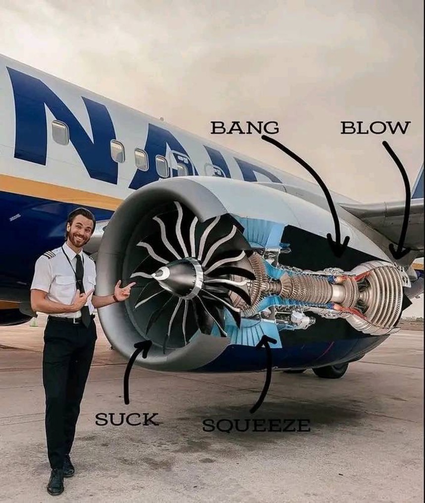
It's tempting to see that huge front fan as "the engine," but the actual gas generator (compressor → combustor → turbine) is the relatively small core buried behind it. The fan is driven by that core through the shaft, and in a high-bypass engine it pushes a large mass of air around the core rather than through it. That bypass flow supplies most of the thrust (often 80%+ on an airliner) — and because it moves a big mass of air slowly rather than a small mass quickly, the propulsive efficiency $\eta_p = 2V_a/(V_5+V_a)$ is far higher. So modern engines lean on the fan precisely because it is the efficient way to make thrust; the core's job is mostly to power the fan.人們很容易把前方那具巨大的風扇看成「引擎」,但真正的燃氣產生器(壓縮機 → 燃燒室 → 渦輪機)其實是藏在其後、相對小巧的核心。風扇是由該核心透過軸帶動的;在高旁通比引擎中,它將大量空氣推向核心周圍而非穿過核心。該旁通氣流提供了大部分推力(客機上常達 80% 以上)——而由於它是緩慢地推動大量空氣、而非快速地推動少量空氣,其推進效率 $\eta_p = 2V_a/(V_5+V_a)$ 遠為更高。因此現代引擎倚重風扇,正是因為它是產生推力的高效方式;核心的主要任務反而是驅動風扇。
Problem set習題集
Two fully worked problems that build the habit — sketch the system → fix every state → mark them on the p–v or T–s chart → apply the governing equations → discuss — and one open-ended design project where you drive an AI to do the analysis.兩道完整詳解的習題,用以養成解題習慣——繪製系統圖 → 確定每個狀態 → 標示於 p–v 或 T–s 圖上 → 套用主導方程式 → 討論——以及一個開放式設計專題,由你引導 AI 進行分析。