What you'll be able to do本章學習成果
- Describe the four-component vapor-compression refrigeration and heat-pump cycles and sketch their T–s diagrams.
- Apply mass and energy balances to evaluate capacity, compressor power, and COP.
- Account for irreversibilities via the isentropic compressor efficiency.
- Explain how varying evaporator and condenser temperatures changes performance, and outline absorption and gas (Brayton) refrigeration.
Key equations重要公式
The vapor-compression cycle蒸汽壓縮循環
The most common refrigeration cycle in use today has four components and four processes. The block diagram below shows how the refrigerant flows around the loop through states 1–2–3–4:
Each numbered point is a state; the four processes that connect them are:
- 4–1 Evaporator: a low-pressure two-phase mixture evaporates, absorbing heat from the refrigerated space.
- 1–2 Compressor: vapor is compressed to high temperature and pressure (work input).
- 2–3 Condenser: vapor condenses to liquid, rejecting heat to the warmer surroundings.
- 3–4 Expansion valve: liquid throttles back to evaporator pressure.
Each component is a steady-state control volume. The compressor is adiabatic; the valve is a throttling process ($h_4 = h_3$, constant enthalpy); kinetic and potential energy changes are ignored. "Dry compression" means the refrigerant entering the compressor is vapor.
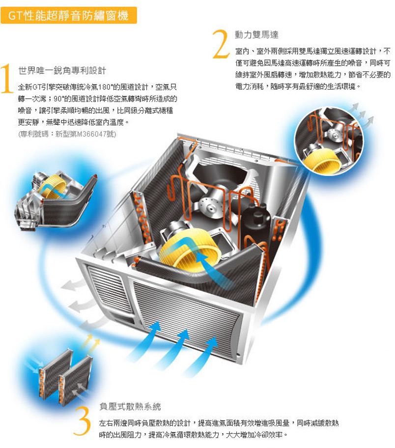
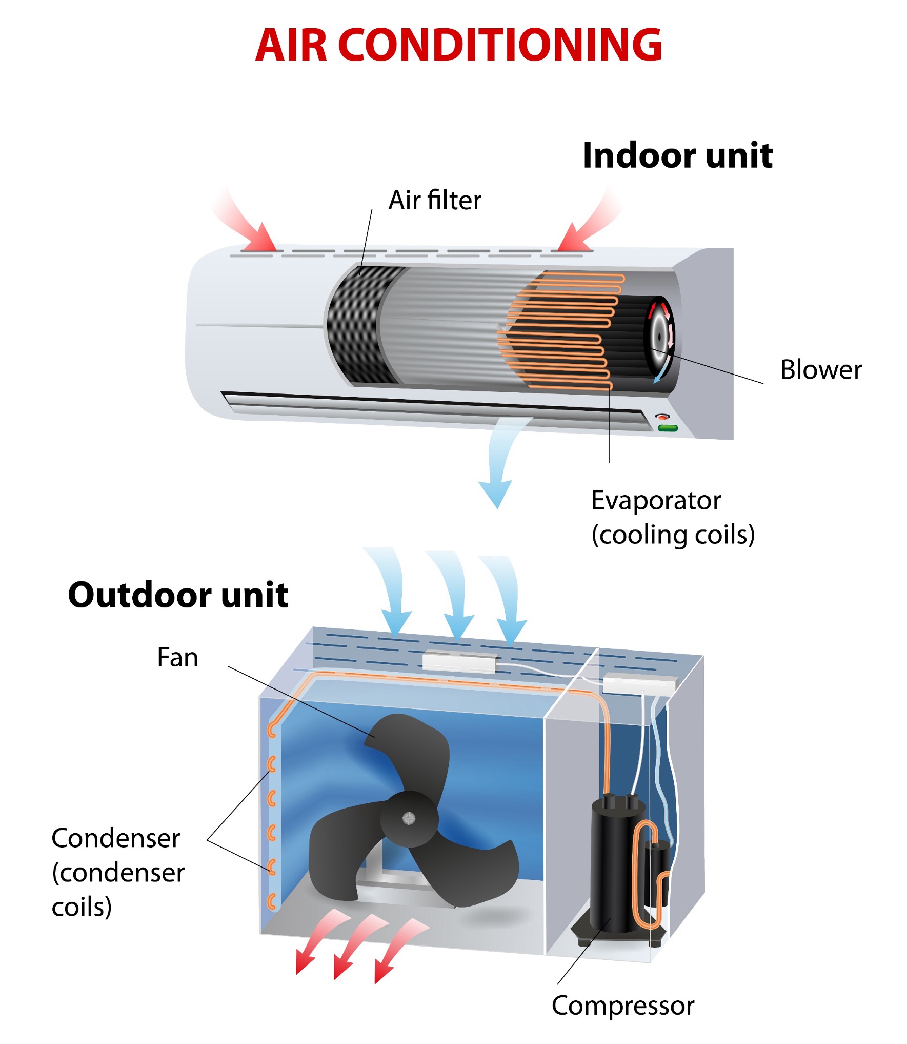
The same four components show up in every household air conditioner — only their packaging differs:
Component balances各組件平衡式
Each component is a steady control volume with one inlet and one exit. Neglecting kinetic and potential energy changes, the steady-flow energy balance (first law) reduces to
Apply it to each component in turn, taking every heat and work transfer as positive in the arrow direction of the schematic. This pins down the sign of $\dot Q_{cv}$ (heat added to the CV) and $\dot W_{cv}$ (work done by the CV) for each case.
Evaporator (4→1). No work crosses the boundary, $\dot W_{cv}=0$; heat is added from the cold space, so $\dot Q_{cv}=+\dot Q_{in}$:
Compressor (1→2). Modeled adiabatic, $\dot Q_{cv}=0$; work is done on the refrigerant, so the work done by the CV is negative, $\dot W_{cv}=-\dot W_c$:
Condenser (2→3). No work, $\dot W_{cv}=0$; heat is rejected to the surroundings, so $\dot Q_{cv}=-\dot Q_{out}$:
Expansion valve (3→4). No work and effectively adiabatic, $\dot Q_{cv}=\dot W_{cv}=0$, so enthalpy is conserved — a throttling process:
Collected together, per unit mass of refrigerant:
The evaporator term $\dot Q_{in}$ is the refrigeration capacity, in kW. A traditional unit is the ton of refrigeration ≈ 211 kJ/min ≈ 3.52 kW.
Coefficient of performance性能係數
Because the "benefit" of a refrigerator is heat removed and the "cost" is compressor work, performance is a coefficient of performance — which can exceed 1:
The maximum theoretical value for any cycle operating between cold and hot regions at $T_C$ and $T_H$ is the Carnot COP:
COP explorerCOP 探索器
Set the evaporator and condenser temperatures and the compressor's isentropic efficiency. The cycle traces on the R-134a T–s diagram while the COP, capacity, and second-law efficiency (vs. Carnot) update. Try narrowing the temperature gap — the COP climbs sharply, exactly as the Carnot limit predicts.
Teaching model on a compact R-134a saturation table; superheated compression approximated with $c_p \approx 0.95$ kJ/kg·K.
Actual vs. ideal cycle實際循環與理想循環比較
Real cycles deviate from the ideal in two ways. Heat transfer is irreversible: the refrigerant must be colder than $T_C$ in the evaporator and hotter than $T_H$ in the condenser, which widens the effective temperature span and lowers COP. And compression is irreversible: entropy rises across the compressor, so the actual work exceeds the isentropic ideal. The isentropic compressor efficiency captures this:
Since the refrigeration effect $h_1-h_4$ is unchanged but the work grows, irreversible compression always lowers the COP. Drag the efficiency slider in the explorer to see it directly.
Heat pumps熱泵
A heat pump uses the identical hardware but its objective is the warm side — keeping a space above ambient. The benefit is now the heat delivered by the condenser:
The cycle, components, and states are identical to the refrigerator; only the objective changes. A refrigerator values the heat pulled from the cold side, $\dot Q_{in}$ (the numerator of $\beta$). A heat pump values the heat delivered to the hot side, $\dot Q_{out}$ (the numerator of $\gamma$). The compressor work $\dot W_c$ is the same "cost" in both denominators — which is exactly why $\gamma = \beta + 1$.
Note $\gamma = \beta + 1$: every unit of work shows up in the delivered heat plus the heat pulled from outdoors, which is why heat pumps can deliver several units of heat per unit of electricity. Toggle the explorer to "Heat pump" mode to compare.
Other refrigeration systems其他製冷系統
- Absorption refrigeration (e.g. ammonia–water) replaces the compressor with an absorber, pump, and generator. Pumping a liquid solution takes far less work than compressing vapor, and the generator can run on waste heat or solar — attractive where cheap heat is available.
- Brayton (gas) refrigeration keeps the working fluid a gas throughout — the reversed Brayton cycle. The turbine helps drive the compressor; used in aircraft and cryogenics.
Choosing a refrigerant選擇冷媒
A vapor-power (Rankine) plant runs on water, but a vapor-compression plant almost never does. The reason is the temperature range. To absorb heat from a cold space the working fluid must boil at the evaporator temperature — often well below 0 °C — and to dump that heat it must condense at the ambient temperature. Water is useless here: it freezes at 0 °C, and to boil it at, say, −10 °C you would need a near-total vacuum (~0.3 kPa), where the vapor is so voluminous the compressor would be absurdly large. A refrigerant is simply a fluid whose saturation dome is positioned for the job: its saturation pressure at the evaporator temperature is near or above atmospheric (manageable equipment), and its critical temperature sits safely above the condensing temperature (so heat can be rejected by condensing). Choosing a refrigerant is choosing a dome that brackets your two operating temperatures.
The trade is never just thermodynamic — it also weighs safety (toxicity and flammability, captured by the ASHRAE A/B + 1/2L/2/3 class) and environmental impact: ozone depletion (CFCs and HCFCs are phased out under the Montreal Protocol) and global-warming potential.
| Refrigerant | Type | Boiling pt (°C) | Critical T (°C) | GWP | Safety | Typical use |
|---|---|---|---|---|---|---|
| R-744 (CO₂) | Natural | −78* | 31 | 1 | A1 | Transcritical systems, cold-climate heat pumps |
| R-717 (NH₃) | Natural | −33 | 132 | 0 | B2L | Large industrial refrigeration, cold storage |
| R-290 (propane) | Natural (HC) | −42 | 97 | 3 | A3 | Small hermetic units, domestic, heat pumps |
| R-32 | HFC | −52 | 78 | 675 | A2L | Residential & commercial AC |
| R-134a | HFC | −26 | 101 | 1430 | A1 | Legacy fridge/AC — being phased down |
| R-1234yf | HFO | −29 | 95 | 4 | A2L | Automotive AC — low-GWP R-134a replacement |
*CO₂ sublimes at atmospheric pressure; it has no normal boiling point.
Global-warming potential measures how much heat a mass of gas traps over a time horizon (usually 100 years) relative to the same mass of CO₂, which is defined as 1. So R-134a at GWP 1430 means a kilogram leaked warms the planet like 1430 kg of CO₂. Because systems inevitably leak, low-GWP fluids are now mandated: the Kigali Amendment and F-gas rules are phasing down high-GWP HFCs toward natural refrigerants (CO₂, ammonia, hydrocarbons) and synthetic HFOs like R-1234yf.
Match the dome to the duty
Each fluid's two-phase dome spans from its boiling point up to its critical point — the temperature band over which it works as a wet vapor. Drag the slider to a target evaporating temperature and watch which refrigerants suit it: a dome must sit low enough to boil there without a deep vacuum, yet have a critical point high enough to condense against the ambient. Click any refrigerant to inspect it.
Vapor-compression performance蒸汽壓縮性能
Example範例 Capacity and COP with R-134aR-134a 的製冷量與 COP ›
Given: R-134a cycle with $h_1=241.4$, $h_2=280.2$, $h_3=h_4=91.5$ kJ/kg and $\dot m=0.08$ kg/s.
Find: compressor power, refrigeration capacity, and COP.
Solution. $$\dot W_c=\dot m(h_2-h_1)=0.08(38.8)=3.1\text{ kW},\quad \dot Q_{in}=\dot m(h_1-h_4)=0.08(149.9)=12.0\text{ kW }(3.4\text{ tons}).$$ $$\beta=\frac{h_1-h_4}{h_2-h_1}=\frac{149.9}{38.8}=3.86.$$
Problem set習題集
Two fully worked problems that build the habit — sketch the plant → fix every state → mark them on the chart → apply the governing equations → discuss. P1 uses the T–s diagram and P2 the p–h (log p–h) diagram — the two charts every refrigeration engineer reads — and a third, open-ended design project has you drive an AI to do the analysis.